This research suggests a unique way to produce charcoal utilizing industrial flue gas as an energy source. The process entails gathering, cleaning, and transporting the flue gas to a pyrolysis reactor where it is used to carbonize and heat biomass. The paper outlined the design of various components, such as the heat exchanger, pyrolysis reactor, and flue gas filter. It specified that the flue gas temperatures in the glass, pulp and paper, and alcohol industries typically range from 400-500°C, 200-500°C, and 150-300°C, respectively. Furthermore, the chemical compositions of these industries were analyzed at the factory. The study emphasized the importance of these design considerations and temperature ranges for efficient operation and optimal performance in the respective industries. The resultant charcoal has several uses and is a sustainable and renewable fuel. In addition, the technique lessens greenhouse gas and flue gas emissions into the atmosphere, protecting the environment and slowing down climate change. The average chemical composition of flue gas from three industries was ascertained, together with the temperature range necessary for pyrolysis and the mechanical layout of the system used to produce charcoal. Upon determining the characteristics of industrial flue gas, the mechanical design of the charcoal production process was incorporated essential components. These include a temporary storage tank, a pyrolysis reactor, and a flue gas filter. This comprehensive design aims to ensure the production of quality charcoal while addressing environmental concerns related to pollution from flue gas treatment. The integration of these components is crucial for optimizing the production process and enhancing environmental sustainability by mitigating the impact of flue gas emissions on the environment. The project report emphasizes the significance of these design considerations in achieving efficient and environmentally friendly charcoal production. The paper also discusses the environmental and economic benefits of using flue gas as an energy source for charcoal production. The paper concludes that this method is a feasible and promising solution for efficient resource utilization and sustainable development.
| Published in | International Journal of Energy and Environmental Science (Volume 9, Issue 1) |
| DOI | 10.11648/j.ijees.20240901.12 |
| Page(s) | 9-19 |
| Creative Commons |
This is an Open Access article, distributed under the terms of the Creative Commons Attribution 4.0 International License (http://creativecommons.org/licenses/by/4.0/), which permits unrestricted use, distribution and reproduction in any medium or format, provided the original work is properly cited. |
| Copyright |
Copyright © The Author(s), 2024. Published by Science Publishing Group |
Industrial Flue Gas, Chemical Compositions Flue Gas, Mechanical Design, Design Analysis
2.1. Manufacturing Process of Charcoal Flue Gas Used as Source of Energy
2.2. The Major Mechanical Design of Pyrolysis Reactor, Heat Exchanger
2.2.1. Fouling Factor
2.2.2. Shell Diameter and Thickness
2.2.3. Shell Cover
2.2.4. Channel Covers Diameter and Thickness
2.2.5. Pass Partition Plate
2.2.6. Tube Sheet Thickness
3.1. Chemical Composition of Flue Gas
Industry | Component | Typical Range (%) | Source |
|---|---|---|---|
Glass industry | Nitrogen oxides (NOx) | 5-15 | Flue gas |
Sulfur dioxide (SO2) | 1-5 | Flue gas | |
Carbon dioxide (CO2) | 10-20 | Flue gas | |
Particulate matter (PM) | 1-5 | Flue gas | |
Pulp & Paper industry | Nitrogen oxides (NOx) | 5-15 | Flue gas |
Sulfur dioxide (SO2) | 1-5 | Flue gas | |
Carbon dioxide (CO2) | 10-20 | Flue gas | |
Carbon monoxide (CO) | 5-10 | Flue gas | |
Alcohol industry | Ethanol (C2H5OH) | 5-10 | Flue gas |
Volatile organic compounds (VOCs) | 1-5 | Flue gas | |
Aldehydes & Ketones | 1-3 | Flue gas | |
Glass industry | Suspended solids (SS) | 5-15 | Effluent |
Organic matter | 10-20 | Effluent | |
Inorganic salts | 5-10 | Effluent | |
Trace metals | 0.1-1 | Effluent | |
Pulp & Paper | Lignin, cellulose | 10-20 | Effluent |
Sugars, organic acids | 5-10 | Effluent |
industry | Flue Gas Temperature Range (°C) |
|---|---|
Glass | 400-1500 |
Pulp & Paper | 200-500 |
Alcohol | 150-300 |
3.2. Mechanical Design of Charcoal Production Process Using Flue Gas as Source of Energy
Mechanical component of pressure vessel | Pressure vessel type | |||||
|---|---|---|---|---|---|---|
Temporary storage tank | Pyrolysis reactor | Heat exchanger | Condenser | Flue gas filter | Water storage tanks | |
Shell diameter | 550mm | 552mm | 250mm | 180mm | 800mm | |
Shell thickness | 10mm | 3mm | 8mm | 5mm | 2mm | |
Shell cover thickness | 10mm | 3mm | 8mm | 5mm | 2mm | |
Channel covers diameter | 552mm | 250mm | 180mm | |||
Channel thickness | 8mm | 5mm | ||||
Pass partition plate | 10mm | |||||
Tube sheet thickness | 3mm | |||||
Impingement plates or baffles | 10mm | |||||
Nozzles and branch pipes | ||||||
Gaskets | ||||||
Bolts design | M20, M16 | M16 | M12, M8 | M12, M8 | ||
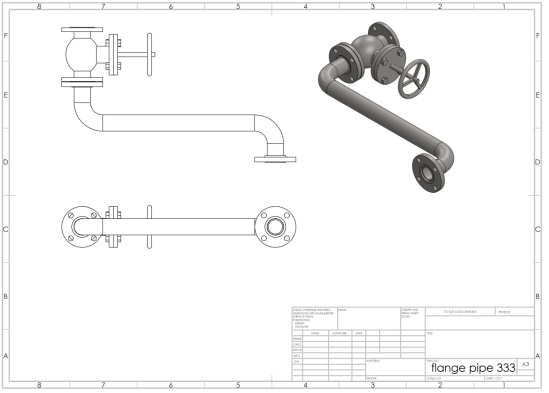
Design of flange | Slip on flange 150, NPS 4 & 8 | Slip on flange 150, NPS 2 | Slip on flange 150, NPS 1 | Slip on flange 150, NPS 1 &2 | ||
Valve | ASME (B16.34) flange end, class 150, NPS 2, RF | ASME (B16.34) flange end, class 150, NPS 1, RF | ASME (B16.34) flange end, class 150, NPS 1, RF | |||
Design of supports | ||||||
| [1] | Adams, D. M. B., & IEA Coal Research. Clean Coal Centre. (2010). Flue gas treatment for CO2 capture (Issue June). |
| [2] | Alrazen, H. A., Aminossadati, S. M., Mahmudul Hasan, M., & Konarova, M. (2023). Effectiveness of co-solvents in boosting LDPE depolymerization in diesel. Fuel, 345 (December 2022), 128135. |
| [3] |
Azzi, M., Day, S., French, D., Halliburton, B., Element, A., Farrell, O., & Feron, P. (2013). Impact of Flue Gas Impurities on Amine - based PCC Plants Final Report. May.
http://www.anlecrd.com.au/projects/impact-of-flue-gas-impurities-on-pcc-plants |
| [4] | Chen, W. H., Biswas, P. P., Ubando, A. T., Kwon, E. E., Lin, K. Y. A., & Ong, H. C. (2023). A review of hydrogen production optimization from the reforming of C1 and C2 alcohols via artificial neural networks. Fuel, 345 (March), 128243. |
| [5] | Cortazar, M., Alvarez, J., Lopez, G., Amutio, M., Artetxe, M., Bilbao, J., & Olazar, M. (2023). Syngas production by bio-oil steam gasification in a fountain confined conical spouted bed reactor. Fuel, 345 (December 2022), 128228. |
| [6] | de las Obras Loscertales, M., Abad, A., García-Labiano, F., Ruiz, J. A. C., & Adánez, J. (2023). Reaction kinetics of a NiO-based oxygen carrier with ethanol to be applied in chemical looping processes. Fuel, 345 (December 2022). |
| [7] | De Simio, L., Iannaccone, S., Iazzetta, A., & Auriemma, M. (2023). Artificial neural networks for speeding-up the experimental calibration of propulsion systems. Fuel, 345 (September 2022), 128194. |
| [8] | Dhoke, C., Cloete, S., Krishnamurthy, S., Seo, H., Luz, I., Soukri, M., Park, Y. ki, Blom, R., Amini, S., & Zaabout, A. (2020). Sorbents screening for post-combustion CO2 capture via combined temperature and pressure swing adsorption. Chemical Engineering Journal, 380 (May 2019), 122201. |
| [9] | Eswaran, M., Rahimi, S., Pandit, S., Chokkiah, B., & Mijakovic, I. (2023). A flexible multifunctional electrode based on conducting PANI/Pd composite for non-enzymatic glucose sensor and direct alcohol fuel cell applications. Fuel, 345 (December 2022), 128182. |
| [10] | Fang, B., Moultos, O. A., Lü, T., Sun, J., Liu, Z., Ning, F., & Vlugt, T. J. H. (2023). Effects of nanobubbles on methane hydrate dissociation: A molecular simulation study. Fuel, 345 (December 2022), 128230. |
| [11] | Frasci, E., Novella Rosa, R., Plá Moreno, B., Arsie, I., & Jannelli, E. (2023). Impact of prechamber design and air–fuel ratio on combustion and fuel consumption in a SI engine equipped with a passive TJI. Fuel, 345 (April). |
| [12] | Glier, J. C., & Rubina, E. S. (2013). Assessment of solid sorbents as a competitive post-combustion CO2 capture technology. Energy Procedia, 37, 65–72. |
| [13] | Guío-Pérez, D. C., Bonmann, M., Bryllert, T., Seemann, M., Stake, J., Johnsson, F., & Pallarès, D. (2023). Radar-based measurements of the solids flow in a circulating fluidized bed. Fuel, 345 (December 2022). |
| [14] | Honecker, C., Lehrheuer, B., Pischinger, S., & Heufer, K. A. (2023). Molecularly-controlled high swirl combustion system for ethanol/1-octanol dual fuel combustion. Fuel, 345 (April), 128184. |
| [15] | IEA Clean Coal Centre. (2009). POST COMBUSTION CARBON CAPTURE FROM COAL FIRED PLANTS-SOLID SORBENTS AND MEMBRANES Technical Study. April. www.ieagreen.org.uk |
| [16] | Jurczyk, M., Mikus, M., & Dziedzic, K. (2016). Flue Gas Cleaning in Municipal Waste- To-Energy Plants – Part II. Infrastructure and Ecology of Rural Areas, February 2017, 1309–1321. |
| [17] | Konopacka-Łyskawa, D., Czaplicka, N., & Szefer, A. (2021). CaO-based high temperature CO2 sorbents - Literature review. Chemical and Process Engineering - Inzynieria Chemiczna i Procesowa, 42(4), 411–438. |
| [18] | Li, H. M., Zhang, N., Guo, X., Dou, M. Y., Feng, Q., Zou, S., & Huang, F. C. (2020a). Summary of Flue Gas Purification and Treatment Technology for Domestic Waste Incineration. IOP Conference Series: Earth and Environmental Science, 508(1). |
| [19] | Li, H. M., Zhang, N., Guo, X., Dou, M. Y., Feng, Q., Zou, S., & Huang, F. C. (2020b). Summary of Flue Gas Purification and Treatment Technology for Domestic Waste Incineration. IOP Conference Series: Earth and Environmental Science, 508(1), 1–8. |
| [20] | López-Toyos, L., López-Antón, M. A., Rodríguez, E., García, R., & Martínez-Tarazona, M. R. (2023). Potential of iron-based composites derived from sucrose foam for mercury removal and safe recovery. Fuel, 345 (September 2022). |
| [21] | Lorentzen, S. J., & Ertesvåg, I. S. (2023). Entropy generation in an opposed-flow laminar non-premixed flame—Effects of using reduced and global chemical mechanisms for methane–air and syngas–air combustion. Fuel, 345 (April), 128263. |
| [22] | Nellie Oduor, Emily Kitheka, Celestine Ingutia, Nathan Nyamai, James Kimwemwe, & Kevin Juma. (2019). Quality and Emission Analysis of Charcoal from Various Species of Wood Using Improved Carbonization Technologies in Kenya. Journal of Environmental Science and Engineering A, 8(1), 16–25. |
| [23] | Nimmo, B., Suuberg, E., Ancheyta, J., Bartocci, P., Brown, R., & Jones, J. (2023). Editorial Board. Fuel, 345, 128421. |
| [24] | Numaguchi, R., Fujiki, J., Yamada, H., Firoz, C. A., Kida, K., Goto, K., Okumura, T., Yoshizawa, K., & Yogo, K. (2017). Development of Post-combustion CO2 Capture System Using Amine-impregnated Solid Sorbent. Energy Procedia, 114 (November 2016), 2304–2312. |
| [25] | Otieno, A. O., Home, P. G., Raude, J. M., Murunga, S. I., & Gachanja, A. (2022). Heating and emission characteristics from combustion of charcoal and co-combustion of charcoal with faecal char-sawdust char briquettes in a ceramic cook stove. Heliyon, 8(8), e10272. |
| [26] | Prus, A. A., Slater, T. D., Marek, E. J., & Hayhurst, A. N. (2023). Using a fluidised bed to measure and investigate the thermal diffusivities and pyrolysis of some woods at temperatures of 200–600°C. Fuel, 345 (March), 128227. |
| [27] | Shao, B., Wang, Z. Q., Gong, X. Q., Liu, H., Qian, F., Hu, P., & Hu, J. (2023). Synergistic promotions between CO2 capture and in-situ conversion on Ni-CaO composite catalyst. Nature Communications, 14(1), 1–10. |
| [28] | Sjostrom, S., & Krutka, H. (2010). Evaluation of solid sorbents as a retrofit technology for CO2 capture. Fuel, 89(6), 1298–1306. |
| [29] | Zhu, Z., & Xu, B. (2022). Purification Technologies for NOx Removal from Flue Gas: A Review. Separations, 9(10), 1–27. |
| [30] | Xu, H., Yao, Y., & Liu, X. (2023). High Throughput Screening for CO2 Capture by MOF Pressure Swing Adsorption Based on Maximum Economic Benefit. 105 (June), 145–150. |
| [31] | Yuan, H., Purnomo, D. M. J., Sun, P., Huang, X., & Rein, G. (2023). Computational study of the multidimensional spread of smouldering combustion at different peat conditions. Fuel, 345 (June 2022), 128064. |
| [32] | Yusuf, N., Almomani, F., & Qiblawey, H. (2023). Catalytic CO2 conversion to C1 value-added products: Review on latest catalytic and process developments. Fuel, 345 (December 2022), 128178. |
| [33] | Zhao, X., Cui, Q., Wang, B., Yan, X., Singh, S., Zhang, F., Gao, X., & Li, Y. (2018). Chinese Journal of Chemical Engineering Recent progress of amine modi fi ed sorbents for capturing CO2 from flue gas. Chinese Journal of Chemical Engineering, 26(11), 2292–2302. |
APA Style
Tekleyohanis, T., Tekleye, A. (2024). Optimizing Industrial Effluent Flue Gas as Source of Energy for Charcoal Production . International Journal of Energy and Environmental Science, 9(1), 9-19. https://doi.org/10.11648/j.ijees.20240901.12
ACS Style
Tekleyohanis, T.; Tekleye, A. Optimizing Industrial Effluent Flue Gas as Source of Energy for Charcoal Production . Int. J. Energy Environ. Sci. 2024, 9(1), 9-19. doi: 10.11648/j.ijees.20240901.12
AMA Style
Tekleyohanis T, Tekleye A. Optimizing Industrial Effluent Flue Gas as Source of Energy for Charcoal Production . Int J Energy Environ Sci. 2024;9(1):9-19. doi: 10.11648/j.ijees.20240901.12
@article{10.11648/j.ijees.20240901.12,
  author = {Tsiye Tekleyohanis and Abebayehu Tekleye},
  title = {Optimizing Industrial Effluent Flue Gas as Source of Energy for Charcoal Production
},
  journal = {International Journal of Energy and Environmental Science},
  volume = {9},
  number = {1},
  pages = {9-19},
  doi = {10.11648/j.ijees.20240901.12},
  url = {https://doi.org/10.11648/j.ijees.20240901.12},
  eprint = {https://article.sciencepublishinggroup.com/pdf/10.11648.j.ijees.20240901.12},
  abstract = {This research suggests a unique way to produce charcoal utilizing industrial flue gas as an energy source. The process entails gathering, cleaning, and transporting the flue gas to a pyrolysis reactor where it is used to carbonize and heat biomass. The paper outlined the design of various components, such as the heat exchanger, pyrolysis reactor, and flue gas filter. It specified that the flue gas temperatures in the glass, pulp and paper, and alcohol industries typically range from 400-500°C, 200-500°C, and 150-300°C, respectively. Furthermore, the chemical compositions of these industries were analyzed at the factory. The study emphasized the importance of these design considerations and temperature ranges for efficient operation and optimal performance in the respective industries. The resultant charcoal has several uses and is a sustainable and renewable fuel. In addition, the technique lessens greenhouse gas and flue gas emissions into the atmosphere, protecting the environment and slowing down climate change. The average chemical composition of flue gas from three industries was ascertained, together with the temperature range necessary for pyrolysis and the mechanical layout of the system used to produce charcoal. Upon determining the characteristics of industrial flue gas, the mechanical design of the charcoal production process was incorporated essential components. These include a temporary storage tank, a pyrolysis reactor, and a flue gas filter. This comprehensive design aims to ensure the production of quality charcoal while addressing environmental concerns related to pollution from flue gas treatment. The integration of these components is crucial for optimizing the production process and enhancing environmental sustainability by mitigating the impact of flue gas emissions on the environment. The project report emphasizes the significance of these design considerations in achieving efficient and environmentally friendly charcoal production. The paper also discusses the environmental and economic benefits of using flue gas as an energy source for charcoal production. The paper concludes that this method is a feasible and promising solution for efficient resource utilization and sustainable development.
},
 year = {2024}
}
TY  - JOUR
T1  - Optimizing Industrial Effluent Flue Gas as Source of Energy for Charcoal Production

AU  - Tsiye Tekleyohanis
AU  - Abebayehu Tekleye
Y1  - 2024/04/11
PY  - 2024
N1  - https://doi.org/10.11648/j.ijees.20240901.12
DO  - 10.11648/j.ijees.20240901.12
T2  - International Journal of Energy and Environmental Science
JF  - International Journal of Energy and Environmental Science
JO  - International Journal of Energy and Environmental Science
SP  - 9
EP  - 19
PB  - Science Publishing Group
SN  - 2578-9546
UR  - https://doi.org/10.11648/j.ijees.20240901.12
AB  - This research suggests a unique way to produce charcoal utilizing industrial flue gas as an energy source. The process entails gathering, cleaning, and transporting the flue gas to a pyrolysis reactor where it is used to carbonize and heat biomass. The paper outlined the design of various components, such as the heat exchanger, pyrolysis reactor, and flue gas filter. It specified that the flue gas temperatures in the glass, pulp and paper, and alcohol industries typically range from 400-500°C, 200-500°C, and 150-300°C, respectively. Furthermore, the chemical compositions of these industries were analyzed at the factory. The study emphasized the importance of these design considerations and temperature ranges for efficient operation and optimal performance in the respective industries. The resultant charcoal has several uses and is a sustainable and renewable fuel. In addition, the technique lessens greenhouse gas and flue gas emissions into the atmosphere, protecting the environment and slowing down climate change. The average chemical composition of flue gas from three industries was ascertained, together with the temperature range necessary for pyrolysis and the mechanical layout of the system used to produce charcoal. Upon determining the characteristics of industrial flue gas, the mechanical design of the charcoal production process was incorporated essential components. These include a temporary storage tank, a pyrolysis reactor, and a flue gas filter. This comprehensive design aims to ensure the production of quality charcoal while addressing environmental concerns related to pollution from flue gas treatment. The integration of these components is crucial for optimizing the production process and enhancing environmental sustainability by mitigating the impact of flue gas emissions on the environment. The project report emphasizes the significance of these design considerations in achieving efficient and environmentally friendly charcoal production. The paper also discusses the environmental and economic benefits of using flue gas as an energy source for charcoal production. The paper concludes that this method is a feasible and promising solution for efficient resource utilization and sustainable development.

VL  - 9
IS  - 1
ER  -
Chemical Engineering, Debre Berhan University, Debre Behan, Ethiopia

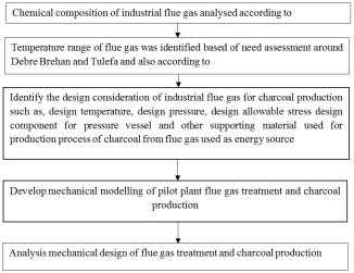
Figure 1. Process flow diagram of flue gas treatment and charcoal production.

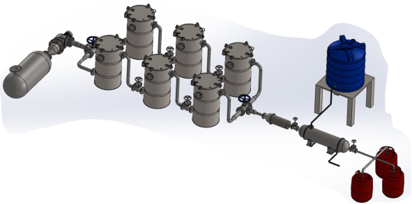
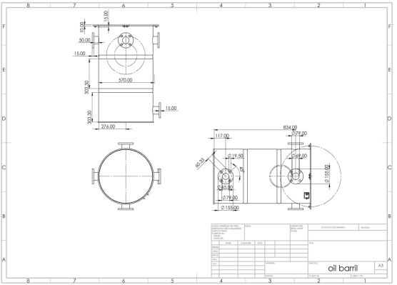
Figure 2. Mechanical Design Assemble of Effluent Flue Gas Used for Charcoal Production.

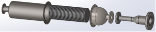
Figure 3. Flue Gas Filter.

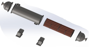
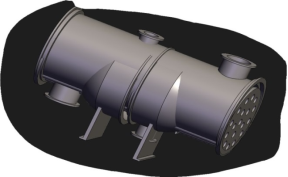
Figure 4. Shell and Tube Heat Exchanger interior View.
Figure 5. Shell and Tube heat exchanger over view.
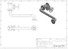
Figure 6. Flange design.

Figure 7. Pyrolysis reactor design.
Information