Abstract
Limited by weight and volume, the transportation and on-site installation of steel bifurcation in the diversion system of pumped storage power station have become a big problem in the construction of the project. According to the needs of the installation and construction of large 800 MPa steel bifurcation in the complex environment, combined with the characteristics of the transportation and installation in the tunnel, the unloading of steel bifurcation is carried out by using the bridge crane between the installation of underground powerhouse. The hoisting up-anchors and sliding trolley arranged in the tunnel are used to place and install the steel bifurcation, which solves the difficulty of hoisting and installing the large turnout pipe in the tunnel and has positive significance in saving the project cost and reducing the construction risk. In this paper, the construction technology of steel bifurcation is described under the complex conditions in pumped storage power station. Detailed description of steel bifurcation construction layout, assembly, site transportation and installation and other construction points, provide a feasible idea for the development of other similar projects.
Keywords
Pumped Storage Power Station, Steel Bifurcation, Complex Environment, Installation, Construction Technology
1. Introduction
The diversion system of Fukang pumped storage power Station in Xinjiang adopts the arrangement of "one hole and two units" and the combination of inclined shaft and horizontal tunnel, and the horizontal distance is about 1815m. The maximum water head of the power station is 524m, the minimum water head is 449m, and the distance to height ratio of the power station is 3.8. Diversion tunnel adopts "one hole two units" arrangement, divided into 1# and 2# two diversion systems. The total length of the 1# diversion tunnel is about 1720m, the total length of the 2# diversion tunnel is about 1690m, the axis direction of the 1 diversion tunnel is NE78.5°, and the axis direction of the 2 diversion tunnel is NE79.3°. The penstock of each diversion system is composed of an upper inclined well, a middle flat hole, a lower inclined well, a lower horizontal hole, a steel bifurcation, and a diversion branch pipe section, and the Angle of the inclined well is 60°.
The diversion system is lined with steel plates from the upper bend of the upper inclined shaft to the inlet of the spiral case. Two symmetrical Y-shaped steel bifurcations are set about 70m upstream of the main plant axis. The bifurcation Angle is 70°, the diameter of the main pipe is 4.6m, the diameter of the branch pipe is 3.2m, and the radius of the common cutting ball is 2.65m, which is 1.152 times that of the main pipe. The design maximum internal water pressure is 840m (including water hammer pressure), the HD value is 3864m2, the steel is Q690E, the pipe wall thickness is 58mm (main switch), the crescent rib thickness is 130mm. The maximum diameter of the common cutting ball is 5.3m. The maximum thickness of steel plate is 56mm and the thickness of rib plate is 130mm. The pipe material is 790MPa, and the weight of a single diversion penstock is about 43 tons. The diameter of the main pipe is 4.6m, the diameter of the branch pipe is 3.2m, and the center elevation of the steel bifurcation is EL.1669.00m.
The cutting, forming and pre-assembly of steel bifurcations are completed in the manufacturing factory, and transported to the site after acceptance, and the overall assembly, welding, water pressure test and transportation installation are carried out in the penstock processing plant on the site.
2. Layout of Construction Site
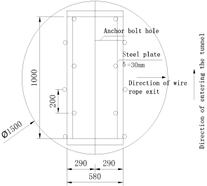
2.1. Layout of the Up-Anchors
According to the height of the construction branch hole and the diameter of the penstock and fork pipe that undertake the transportation task, the size of the expanded up-anchors hole is determined, and the number of anchor bolts is determined according to the maximum pipe joint weight of the penstock. The section of the branch tunnel is round, the opening diameter is 4.5m, the top diameter is 1.5m, and the depth is 4.5m. During the expansion of the tunnel, the surrounding holes are blasted plain, and 8cm thick concrete is sprayed.
After the excavation of the up-anchors hole is completed, the anchor rod construction will be carried out. The bolt size is 32mm in diameter, 4m in length, 3.5m into the rock, and the Angle is 30 degrees. The number of bolts is 12, and the hole diameter is 42mm. During the construction of bolts, pay attention to laying holes according to the positions marked in the drawings, and strictly control the Angle and depth when making holes. The bolt adopts mortar bolt. After the completion of the bolt construction, a single bolt should be pulled out test. After passing the test, δ=30mm steel plates can be welded on the bolt to connect all the bolts to form an overall bracket, as shown in
Figure 1. After the installation of all lifting equipment, load tests should be carried out in accordance with the requirements of the code, and the test results can be put into use
| [1] | Li Bing, Chang Yong, Chen Shangui, et al. (2020). Research on welding quality control technology of steel bifurcation in large pumped storage power station [J]. Hydropower and Pumped Storage, 6(3): 4. |
| [2] | Yao Minjie, Wang Jian-Guo, Li Gao-hui, et al. (2021). Study on Optimization of Large-diameter three-beam steel bifurcation at the bottom of diversion surge chamber of a pumped storage power station [J]. DAM & Safety. |
[1, 2]
.
Figure 1. Up-anchors Diagram.
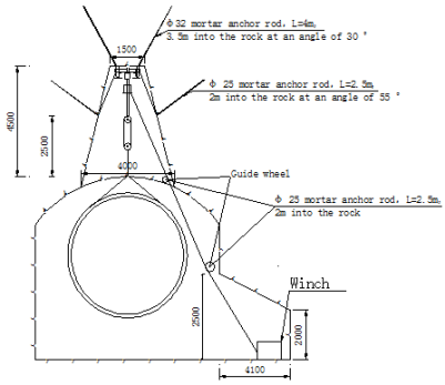
2.2. Layout of Hoisting System
After the completion of the excavation at the up-anchors layout, a 5m length (in both directions perpendicular to the cave entrance direction), a depth of 4.1m and a height of 7 degrees inward along the cave wall of 2.5m should be dug at the center of the up-anchors along the right side of the cave entrance direction. During the excavation, the spatial arrangement of the hoisting system should be used to blast the smooth surface of the surrounding holes and spray 8cm thick concrete. After the excavation is completed, the position of the ground anchor of the hoist is determined. The specifications of the embedded anchor rod are 25mm in diameter, 3m in length, 2.5m in rock, 7 in number, 42mm in diameter and 2.5m in depth, and the anchor rod is made of mortar.
2.3. Layout of Up-Anchor and Winch Guide Bolt
After the position of the up-anchors and the winch is completely determined, the guide arrangement of the wire rope between the up-anchors and the winch is carried out. According to the actual investigation, the guide should be arranged in two places, so the anchor rod should be embedded in advance. The diameter of the embedded anchor rod is 25mm, the length is 3m, the rock is 2.5m, the number is 16 (including the support of the up-anchors), the hole size is 42mm in diameter and the depth is 2m. The bolt adopts mortar bolt. Unload the up-anchors refer to
Figure 2.
Figure 2. Schematic Diagram of Unloading with Up-anchor.
2.4. Layout of Steel Bifurcations Installation Construction Unloading and Hoisting in the Tunnel
The steel bifurcation trailer truck is transported to the installation room of the underground plant, and the 300 tons bridge machine is used to unload the truck to the transport platform car. When the loader is pulled from the traffic tunnel into the plant to the entrance of the 4# branch hole, the 12t hoist steel wire rope is connected to the switch pipe bracket through the ground anchor downstream of the switch pipe installation site for transportation until it is transported to the installation position. When the switch pipe is transported on the track, a stop block is set at the lower part of the bracket to prevent the switch pipe from falling off the track during transportation. The transport layout of steel bifurcation pipe refer to
Figure 3.
Figure 3. Layout of Steel Bifurcation Transportation.
2.5. Layout of Tunnel Transport Track
Lay the temporary transportation track from the installation section to the entrance of the plant traffic tunnel to the entrance of the 4# branch hole, and from the entrance of the 4# branch hole to the unloading anchor of the 4# branch hole. The transportation track in the 4# construction branch hole is laid with 60x40mm solid square steel, and the track in the high-pressure branch pipe (bifurcated pipe) section is laid with I20a I-steel, and the high-pressure branch pipe (bifurcated pipe) track spacing is 2 meters. All the tracks are arranged in the center of the hole, the deviation of the track center line is 10mm, the elevation deviation is ±5mm, and the relative elevation difference is 5mm.
Before the installation of the construction branch tunnel track, the anchor rod is driven in advance to determine the installation position of the track. After the track is installed, it is welded to the anchor rod on both sides for welding reinforcement
| [3] | Yu Jian, Liu Rui, Yu Ran. (2021). Research on design optimization and technology of high-strength steel bifurcation in Fengning Pumped Storage Power Station, Hebei Province [J]. Hydropower Automation and Dam Monitoring, 2021(001): 007. |
| [4] | Dai Guiyou. (2019). Discussion on unconventional Installation Technology of Large Steel bifurcation [J]. CITY ST RIES, (2): 2. |
[3, 4]
. The track in the construction branch tunnel is arranged on the ground, which can meet the traffic of concrete transport vehicles and other vehicles after installation. Before installing the track, the anchor rod is driven in advance to determine the installation position of the track. After the track is installed, the steel support is welded to the anchor rod on both sides for connection and reinforcement
| [5] | Zhu Shuqing, Du Sha, Li Xiaofang. (2020). Application Practice of 800 MPa Large Size and High Strength Steel Plate on High pressure turnout pipe [J]. Yellow River. |
[5]
.
3. Integrated Assembly of Steel Bifurcation
3.1. Assembly of Steel Bifurcation
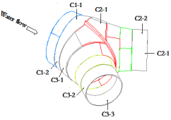
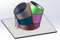
The steel bifurcation is divided into five parts, which are: main switch pipe C1, main switch pipe C2, main switch pipe C3, and support cone pipe, which are assembled as a whole after forming. Tile segmentation refers to
Figure 4.
Figure 4. Schematic Diagram of Tile Segmentation.
The assembly of the steel bifurcation is carried out in the penstock processing plant on the site, and the vertical assembly method is adopted, that is, the cross section of the pipe mouth is placed parallel to the ground direction. As shown in
Figure 5, the gantry crane of the penstock processing plant and the original lifting lug are used to assemble the turnout pipe.
Figure 5. Schematic Diagram of Steel Bifurcation Assembly Model.
(1) Adjust the process platform and draw the plot line
The overall flatness of the process platform is adjusted to within 0.5mm and fixed firmly to prevent positioning during preassembly. Draw the diameter of the upper and lower pipe ports of C1 and the center point of the equipment, and make marks.
(2) C1 segment assembly
Lift the C1 segment tile onto the platform according to the size line drawn, pay attention to the C1 segment mouth downward, the small mouth coincide with the ground transect line is qualified, and measure the diameter of the big mouth and the distance between the center point and the inner wall of the segment, check the ellipticity and concentricity of the entire segment, check the overlap between the big mouth and the ground transect line, and lift a line drop every 200~300mm in the circumference direction. According to the theoretical size of the computer lofting, check the distance between the big mouth and the plane, which conforms to the theoretical value, and the error between the suspended line and the theoretical value is controlled within 2mm. In case of excess, it is necessary to adjust the height by means of jack calibration and grinder grinding.
(3) C2-1 segment preinstalled
The C2-1 segment was pre-installed on C1 segment according to the drawing and the following figure. The inner diameter of the size and size mouth and the distance between the center point and the inner wall were measured, and the ellipticity and concentricity of the segment were checked. The hanging line checks the overlap between the small mouth and the large mouth and the ground sample, and hangs a line drop every 200~300mm in the circumference direction. According to the theoretical size of the computer lofting, check the spacing between the small mouth, the large mouth and the process platform, and the theoretical value shall be subject to the standard, and the error between the hanging line and the theoretical value shall be controlled within 2mm. In case of excess, it is necessary to adjust the height by means of jack calibration and grinder grinding. After all dimensions are checked and qualified, spot weld the fixed positioning block in strict accordance with the requirements and fix the C2-1 segment on the C1 segment.
(4) Crescent rib assembly
Hoist the crescent rib on C1 segment as a whole, check the fit between the crescent rib and C2-1 segment, the clearance between the crescent rib and C2-1 segment is qualified within the technical requirements, check the verticality between the crescent rib and the process platform, and the spacing error between the center point is qualified within the control range
| [6] | Gong Hong, YUE Tingwen, WAN Tianming. (2018). Discussion on the operation and installation technology of high-strength steel switch [C]// The 9th National Academic Conference on Pressure Pipeline of Hydropower Station. China Society for Hydropower Engineering. |
[6]
.
(5) Other segment assembly
Assemble C3-1 segment, C2-2 segment, C2-3 segment and C3-2 segment, C3-3 segment in turn according to requirements.
(6) Overall inspection, installation and welding of positioning plate
The above sections and crescent rib plates are pre-installed, and after acceptance by relevant personnel, the positioning block is welded and marked. According to the marks between sections, assembly inspection, dimensional inspection, witness acceptance as required.
3.2. Welding of Steel Bifurcation
Steel bifurcation adopts symmetrical welding, before welding, the assembly of the main components should be checked, and the deviation should be corrected in time. When welding, the welding line energy remains stable throughout the welding process. In order to minimize deformation and shrinkage stress, the positioning welding spot and welding sequence should be selected before welding from the parts with greater constraints around the component, and advanced to the parts with less constraints. Auxiliary welding plates for starting and extinguishing arc shall be provided for longitudinal seam welding. It is strictly forbidden to initiate and extinguish arc on the base metal. Arc initiation and quenching of positioning welding should be carried out in the groove
| [7] | Wang Bo, Wen Chen, Ma Guodong, et al. (2018). Assembly and Welding technology of high-strength water diversion steel bifurcation [C]// Pumped Storage Power Station Project Construction collection 2018. |
| [8] | Yang Liandong. (2015). Integrated Transportation and Installation Technology of turnout pipe in tunnel under complex environmental conditions [J]. South-to-North Water Transfers and Water Science & Technology, 13(S01): 225-227. |
| [9] | Yang Lina, He Zhao-sheng, JIANG Dong-bo. (2021). Study on layout and optimal design of diversion system for Grade 7 Nanoujiang Hydropower Station [J]. SHUILI SHUIDIAN SHIGONG, 000 (002): P. 11-13. |
| [10] | Jiang Lei. (2016). Field Transportation and Analysis of Steel bifurcation in CCS Hydropower Station [J]. Mechanical & Electrical Technique of Hydropower Station, 39(9): 4. |
[7-10]
. The indirect head of multi-layer welding should be staggered, the weld joints of electrode arc welding, semi-automatic gas shielded welding and self-shielded fluxcored wire welding should be staggered by more than 25mm, and the submerged arc welding, melting and automatic gas shielded welding and self-shielded fluxcored wire automatic welding should be staggered by more than 100mm.
Each weld should be continuously welded once, when the welding is interrupted for some reason, anti-crack measures should be taken. The temperature between the welding layers should not be lower than the preheating temperature, and the high strength steel should not be higher than 200°C.
After the welding is completed, the weld seam non-destructive inspection shall be carried out. All welds of the switch pipe shall be 100% ultrasonic inspection, supplemented by 40% TOFD inspection and 100% magnetic particle inspection. Non-destructive testing should be carried out 48 hours after the welding is completed, and 100% colored penetration testing should be carried out after the hydraulic test
.
After the steel bifurcation is assembled and welded in the penstock processing plant, the water pressure test is carried out, and the anticorrosion is carried out according to the requirements after passing
.
4. Water Pressure Test of Steel Bifurcation
Hydraulic test to check the steel switch and welding construction quality, expose structural defects, verify the overall reliability of the structure. And reduce the welding residual stress, partially eliminate the tip stress of the discontinuous parts of the steel bifurcation and passivate the pointed defects (because the defect size is less than the sensitivity of non-destructive inspection), prevent the expansion of the defects, and provide a reliable guarantee for the long-term safe operation of the steel bifurcation. At the same time, through testing the working stress in the process of hydraulic test, the stress distribution law is found out and verified with the results of finite element analysis
| [13] | Gong Feng, Yan Qi. (2020). Fabrication and Hydraulic Test of 800MPa High strength Steel bifurcation in Yimeng Pumped Storage Power Station [J]. SHUILI SHUIDIAN SHIGONG, 000(002): P. 115-118. |
[13]
.
The main test contents of hydraulic test include: welding residual stress test before and after hydraulic test, hydraulic test stress test, steel bifurcation deformation test, water volume test - pressure curve test and water temperature test in turnout pipe during hydraulic test.
The water pressure test of steel bifurcation is divided into two stages: prepressure test and water pressure test. The hydraulic test loading method adopts repeated step by step loading and slow pressurization to reduce part of the residual stress caused by the processing technology, so that the local stress of the structure is adjusted and homogenized, and tends to be stable, so that the test data can reflect the elastic condition of the bifurcated pipe. In the process of hydraulic test, the loading speed should not be greater than 0.05MPa/min, and the pressure should be stabilized for 10min per pressure boost
.
5. Transportation and Installation of Steel Bifurcation
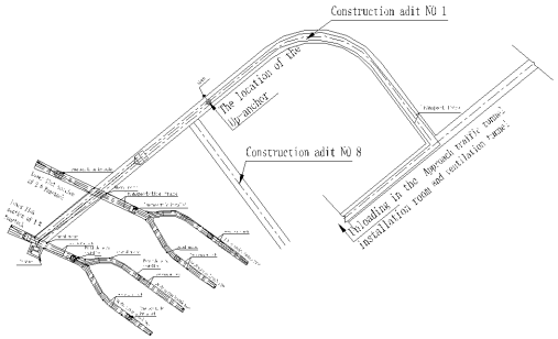
The original transportation route of the steel switch is: loading and transportation of the steel switch →1# highway → incoming traffic tunnel → Unloading of the steel switch at the anchor before the intersection of the 4# construction branch tunnel and the 8# construction branch tunnel → Lifting the steel switch to the transport truck → Hoisting the steel bifurcation to the working face of the installation site. Due to the fact that the size of the section at the intersection of the inbound traffic tunnel and the No. 4 construction branch tunnel cannot ensure the transportation passage of the steel bifurcation, it is necessary to carry out expansion excavation. Affected by the geological conditions of the underground workshop, the geological conditions of the expansion area are poor, and there is a large safety risk in the expansion excavation.
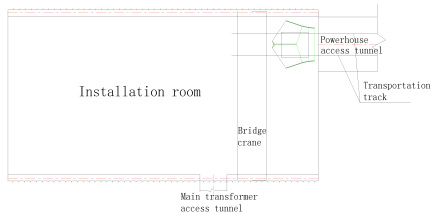
In order to meet the requirements of steel bifurcation transportation, the transportation route is adjusted to: Loading and transportation of steel bifurcation →1# highway → entering the factory traffic tunnel → Unloading of 300 tons of steel bifurcation by underground workshop → Lifting the steel bifurcation onto the transport platform → pulling the steel bifurcation by the loader to the opening of the 4# branch hole → Turning the wheel of the transport trolley into the 4# branch hole → Pulling the steel bifurcation to the working face of the installation site by the 4# branch hole winch, Unloading transport between installation of steel bifurcation refer to
Figure 6.
Figure 6. Schematic Diagram of Unloading and Transportation in the Installation room of Steel Bifurcation.
In this way, it is necessary to add the temporary transportation track between the installation section and the entrance tunnel to the 4# branch tunnel entrance, and the 4# branch tunnel entrance to the 4# branch hole unloading up-anchors. After the steel bifurcation is transported to the installation room by the pallet truck through the incoming traffic hole, the 300-ton bridge in the installation room of the underground plant is unloaded to the transport platform car, and the loader is pulled from the incoming traffic hole to the opening of the 4# branch hole. When the trolley is transported to the incoming traffic hole and the crossing position with the 4# main hole, the traction is stopped. At this time, the transport trolley track is just docked with the main hole track of the 4# branch hole. Four 20t jacks are used to lift the trolley and the penstock in parallel, rotate the transport wheel of the trolley 90 degrees, remove the jack, and then use the loader and 12t hoist arranged in the 4# construction branch hole to pull and transport to the installation position of the steel bifurcation.
The control point is the lower and middle position of the three ports of the turnout pipe. Because the three axial adjustments are involved, the installation position must be adjusted several times. When adjusting, 12T winch with 50t mechanical jack and 16t jack are used. After initial adjustment, I20a I-steel is used to weld steel bench at the lower part of the switch pipe, and then the jack is used to adjust. After the adjustment is completed, the turnout pipe is initially strengthened, and the reinforcement position is 400mm away from each pipe mouth of the turnout pipe, and it is firmly connected to the lifting lug of the outer wall of the turnout pipe and the anchor rod of the rock wall. It is strictly prohibited to strengthen and weld directly on the outer wall of the turnout pipe. There is no anchor rod in the contact position of the reinforcement material and the rock wall.
(1) Concrete placement
After the overall installation and reinforcement of the turnout pipe is completed, the concrete is poured, and the position of the turnout pipe is monitored at any time during the pouring process to ensure the installation accuracy of the turnout pipe.
(2) Bifurcated pipe welding
The welding process of turnout pipe is carried out in accordance with the process parameters of the welding process evaluation results of the corresponding material. The annular joint of the turnout pipe is installed by welding rod arc welding. After the welding, appearance inspection, non-destructive testing and defect treatment are carried out according to the requirements of the design technical requirements and the requirements of the GB50766-2012 specification
| [15] | Qin Kuntao, Li Fengchao. (2016). Welding process of steel bifurcation in Xianju pumped Storage Power Station [J]. China Venture Capital, 000(008): 129-129. |
[15]
.
6. Conclusion
The transportation and installation of steel bifurcation of factor system of pumped storage power station can be effectively transported to the specific installation site through the tunnel of entering the plant and the construction of branch holes under the horizontal section of diversion water. By using this technology, the assembly, transportation and installation of steel bifurcations are generally safe and reliable, and basically will not affect the progress of the overall project.
In this paper, the construction layout, assembly, transportation and installation of steel bifurcation in pumped storage power station under various complex conditions at high altitudes, cold areas and construction sites are analyzed. From an objective point of view, the assembly, transportation and installation of steel bifurcation in the construction process of pumped storage power station at this stage can basically obtain ideal results. Many works are carried out in accordance with correct principles and norms, and the results obtained are worthy of recognition. In the future, differentiated construction methods of steel bifurcations should be selected for different regions to improve the level of construction technology and create greater benefits.
Conflicts of Interest
The authors declare no conflicts of interest.
References
| [1] |
Li Bing, Chang Yong, Chen Shangui, et al. (2020). Research on welding quality control technology of steel bifurcation in large pumped storage power station [J]. Hydropower and Pumped Storage, 6(3): 4.
|
| [2] |
Yao Minjie, Wang Jian-Guo, Li Gao-hui, et al. (2021). Study on Optimization of Large-diameter three-beam steel bifurcation at the bottom of diversion surge chamber of a pumped storage power station [J]. DAM & Safety.
|
| [3] |
Yu Jian, Liu Rui, Yu Ran. (2021). Research on design optimization and technology of high-strength steel bifurcation in Fengning Pumped Storage Power Station, Hebei Province [J]. Hydropower Automation and Dam Monitoring, 2021(001): 007.
|
| [4] |
Dai Guiyou. (2019). Discussion on unconventional Installation Technology of Large Steel bifurcation [J]. CITY ST RIES, (2): 2.
|
| [5] |
Zhu Shuqing, Du Sha, Li Xiaofang. (2020). Application Practice of 800 MPa Large Size and High Strength Steel Plate on High pressure turnout pipe [J]. Yellow River.
|
| [6] |
Gong Hong, YUE Tingwen, WAN Tianming. (2018). Discussion on the operation and installation technology of high-strength steel switch [C]// The 9th National Academic Conference on Pressure Pipeline of Hydropower Station. China Society for Hydropower Engineering.
|
| [7] |
Wang Bo, Wen Chen, Ma Guodong, et al. (2018). Assembly and Welding technology of high-strength water diversion steel bifurcation [C]// Pumped Storage Power Station Project Construction collection 2018.
|
| [8] |
Yang Liandong. (2015). Integrated Transportation and Installation Technology of turnout pipe in tunnel under complex environmental conditions [J]. South-to-North Water Transfers and Water Science & Technology, 13(S01): 225-227.
|
| [9] |
Yang Lina, He Zhao-sheng, JIANG Dong-bo. (2021). Study on layout and optimal design of diversion system for Grade 7 Nanoujiang Hydropower Station [J]. SHUILI SHUIDIAN SHIGONG, 000 (002): P. 11-13.
|
| [10] |
Jiang Lei. (2016). Field Transportation and Analysis of Steel bifurcation in CCS Hydropower Station [J]. Mechanical & Electrical Technique of Hydropower Station, 39(9): 4.
|
| [11] |
Lu Yan. (2018). Xianju hydropower station water diversion system of the steel bifurcation pipe assembly and welding process control [J]. KEJIFENG, (20): 1. From
https://doi.org/10.19392/j.carolcarrollnki.1671-7341.201820156
|
| [12] |
Xie Yuqi. (2021). Pumped storage power plant steel bifurcation pipe hydraulic test technical analysis [J]. From
https://doi.org/10.12159/j.i SSN.2095-6630.2021.10.0082
|
| [13] |
Gong Feng, Yan Qi. (2020). Fabrication and Hydraulic Test of 800MPa High strength Steel bifurcation in Yimeng Pumped Storage Power Station [J]. SHUILI SHUIDIAN SHIGONG, 000(002): P. 115-118.
|
| [14] |
Hu Wangxing, Su Junan. (2010). Liyang pumped storage power plant design and construction of water diversion steel bifurcation pipe technology research [J]. Water Power, 36(7): 4.
https://doi.org/10.3969/j.iSSN.0559-9342.2010.07.013
|
| [15] |
Qin Kuntao, Li Fengchao. (2016). Welding process of steel bifurcation in Xianju pumped Storage Power Station [J]. China Venture Capital, 000(008): 129-129.
|
Cite This Article
-
APA Style
Ruoyu, Z. (2024). Research on Construction Technology of Steel Bifurcation for Diversion System in Pumped Storage Power Station Under Complex Conditions. American Journal of Water Science and Engineering, 10(1), 1-7. https://doi.org/10.11648/j.ajwse.20241001.11
 Copy
|
Copy
|
 Download
ACS Style
Ruoyu, Z. Research on Construction Technology of Steel Bifurcation for Diversion System in Pumped Storage Power Station Under Complex Conditions. Am. J. Water Sci. Eng. 2024, 10(1), 1-7. doi: 10.11648/j.ajwse.20241001.11
Copy
|
Download
AMA Style
Ruoyu Z. Research on Construction Technology of Steel Bifurcation for Diversion System in Pumped Storage Power Station Under Complex Conditions. Am J Water Sci Eng. 2024;10(1):1-7. doi: 10.11648/j.ajwse.20241001.11
Copy
|
Download
-
@article{10.11648/j.ajwse.20241001.11,
  author = {Zhou Ruoyu},
  title = {Research on Construction Technology of Steel Bifurcation for Diversion System in Pumped Storage Power Station Under Complex Conditions
},
  journal = {American Journal of Water Science and Engineering},
  volume = {10},
  number = {1},
  pages = {1-7},
  doi = {10.11648/j.ajwse.20241001.11},
  url = {https://doi.org/10.11648/j.ajwse.20241001.11},
  eprint = {https://article.sciencepublishinggroup.com/pdf/10.11648.j.ajwse.20241001.11},
  abstract = {Limited by weight and volume, the transportation and on-site installation of steel bifurcation in the diversion system of pumped storage power station have become a big problem in the construction of the project. According to the needs of the installation and construction of large 800 MPa steel bifurcation in the complex environment, combined with the characteristics of the transportation and installation in the tunnel, the unloading of steel bifurcation is carried out by using the bridge crane between the installation of underground powerhouse. The hoisting up-anchors and sliding trolley arranged in the tunnel are used to place and install the steel bifurcation, which solves the difficulty of hoisting and installing the large turnout pipe in the tunnel and has positive significance in saving the project cost and reducing the construction risk. In this paper, the construction technology of steel bifurcation is described under the complex conditions in pumped storage power station. Detailed description of steel bifurcation construction layout, assembly, site transportation and installation and other construction points, provide a feasible idea for the development of other similar projects.
},
 year = {2024}
}
Copy
|
Download
-
TY  - JOUR
T1  - Research on Construction Technology of Steel Bifurcation for Diversion System in Pumped Storage Power Station Under Complex Conditions

AU  - Zhou Ruoyu
Y1  - 2024/04/02
PY  - 2024
N1  - https://doi.org/10.11648/j.ajwse.20241001.11
DO  - 10.11648/j.ajwse.20241001.11
T2  - American Journal of Water Science and Engineering
JF  - American Journal of Water Science and Engineering
JO  - American Journal of Water Science and Engineering
SP  - 1
EP  - 7
PB  - Science Publishing Group
SN  - 2575-1875
UR  - https://doi.org/10.11648/j.ajwse.20241001.11
AB  - Limited by weight and volume, the transportation and on-site installation of steel bifurcation in the diversion system of pumped storage power station have become a big problem in the construction of the project. According to the needs of the installation and construction of large 800 MPa steel bifurcation in the complex environment, combined with the characteristics of the transportation and installation in the tunnel, the unloading of steel bifurcation is carried out by using the bridge crane between the installation of underground powerhouse. The hoisting up-anchors and sliding trolley arranged in the tunnel are used to place and install the steel bifurcation, which solves the difficulty of hoisting and installing the large turnout pipe in the tunnel and has positive significance in saving the project cost and reducing the construction risk. In this paper, the construction technology of steel bifurcation is described under the complex conditions in pumped storage power station. Detailed description of steel bifurcation construction layout, assembly, site transportation and installation and other construction points, provide a feasible idea for the development of other similar projects.

VL  - 10
IS  - 1
ER  -
Copy
|
Download